|
| |
|
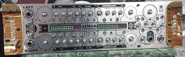
Developed in collaboration
with Australian multi-award winning Producer/Engineer David
Nicholas (US & UK #1s with Pulp, INXS, Elton John, Bryan Adams)
the Prodigal Dual Channel Strip & Monitor Station is a
world class analog strip for use in pro studio, location, or
home recording and mastering. This blog follows a single unit
through a typical production build. |
|
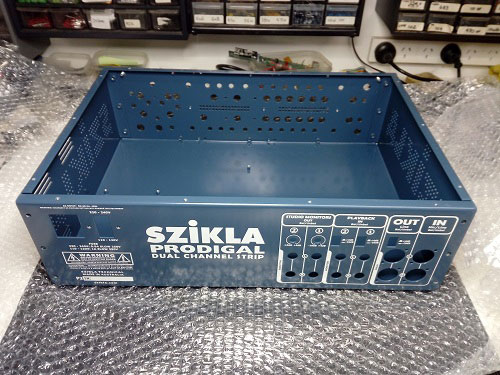
1. Empty Chassis.
Straight out of bubble-wrap and ready to begin. |
|
 |
|
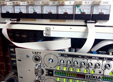
2. Power Supply Installed.
Includes IEC inlet, Voltage Selector, and front panel Power
Switch. |
|
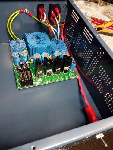 |
The Prodigal uses 3 Torroidal Power Transformers
instead of the cheaper option of a single one with lots of
output windings that magnetically couple. This means that the VU and
relay circuits are completely isolated from the analog audio
circuitry - for super silent running. A third transformer feeds only the P48 supply.
Rail
voltages produced are:
T1: +48 phantom
T2: +15, +9, -9, -15 audio
T3: +5 digital metering, +12 relay switching.
Note the Star Ground Post on the rear panel,
which is the only point where Safety, Analog, Digital,
and Chassis Grounds meet. From any point in the
Prodigal's circuitry, there is only one path back to
here, which eliminates internal ground-loops and current noise
from neighbouring circuit nodes. This simple idea can be
challenging to implement, but is a big factor in creating the
Prodigal's scarily quiet noise floor. The Monitor Section alone
boasts a signal to noise ratio of 104dB!
Keen observers will also notice there is no electric fan
to annoy you during mixing. Fans in audio gear, well, blow. The
Prodigal is designed to run cool, and only needs the four small
black heatsinks for the audio rails, to which an additional
cooling fin will be added later in the build process.
|
|
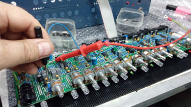
3. Pre-Assembly Test and
Alignment.
All Boards |
|
 |
Prior to assembly, all boards are tested against
a massive checklist to ensure there are no mistakes in the
build, and that they operate within their designated electrical
parameters.
Voltages, current consumption, signal levels, gain and switching
are checked and adjusted where applicable.
One of the finer settings performed is alignment of the
electronics behind the 0 to 30dB Input Gain knob, which is
tweaked to a tolerance of one hundredth of a dB. Also, to overcome
the tremendous imprecision of logarithmic pot tapers, this gain
section boasts an innovative design wherein a linear potentiometer
enslaves a cascading pair of op-amps in a highly mathematical way. Across
30dB of adjustment, the gain curve tracks to within 1dB
of a perfect log law.

Special matched components are also installed at this time, such
as the gain-reduction FETs (one for the De-Esser and one for the
Compressor) which need to operate in perfect concert between Left and
Right channels. Pre-calibrated parts are soldered in
sequence, then each board pair is numbered and kept together
during the
rest of construction. |
|
4. Pre-Assembly Test and
Alignment. Microphone Preamplifier
(egghead
 warning!)
 |
Input Amplification Test |
Special treatment is given to the commissioning of
the Microphone Preamp board.
The Prodigal has no input transformer to deliver
a free level-boost prior to
amplification. The Mic signal is taken directly into the preamp, so
every part of the front end has to be sweet and clean.
Transistors are hand-matched and thermally paired
for super low-noise operation. Input resistors are also matched,
and impedances are kept on the low side of the IEC permitted
range. That's because we think audio signals sound better when
driving a lower impedance. Raise an eyebrow if you like, but we've done
double-blind tests and folks can hear the difference; now it's
part of the Prodigal sound. Unlike transformers, resistors also
present a uniform input impedance across all frequencies. We
like that too.
With Mic inputs, switching is important. You need to be able
to change level and impedance between mic and line, apply a 20dB
pad, invert phase, and apply 48v phantom. With the main inputs
at rear, mic signals would have to travel a long way exposed to
other circuitry before arriving at the front-panel switches, and
in cheapo devices that's how it works. In the Prodigal we take
the switches to the back panel instead
–
via high
quality relays. The switches switch the relays, and the relays
switch the audio. That keeps the signal path short, and delivers
the cleanest possible soundwave prior to amplification.
Mic levels are very small, and fluctuations on the
power lines can cause large harmonic distortions if they bleed
through. On each mic amp power supply, the Prodigal uses a zener-referenced
regulator circuit which subdues about 10,000 times more voltage
flutter than an on-chip regulator. Zener diodes are
classified as being of a fixed voltage, but the volts actually
vary with the current passing through them
–
as the graph on the
left shows. We use 1N4735A vintage Motorola diodes (the blue
line) which are not made any more. You can see as current
increases there is a flat spot where the voltage
doesn't change. We run the Motorolas right in that spot,
at 58 microamps bias. That means Thor (the mighty god of ending
your career) can zap your power supply with a 50% voltage spike,
causing a 50% change in diode current, and the result
will be (at 38 or 87uA) NO change of zener voltage and the microphone amp won't
even notice.
We continue to blow our lunch money testing
modern diodes (even with the SAME PART NUMBER) and so far
they're all useless
– no flat spot, so
no gig. Five
are on the graph, but we've tried heaps.
Pre-assembly testing looks at all the above, plus
a bunch of less interesting housekeeping. I like the photo of the
Motorola diode. He's a sexy boy.
|
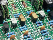
Transistors Matched and Paired |
High Dependability
Axicom Relays |
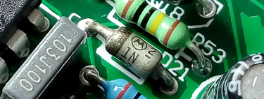
Vintage Motorola Silver Reference Diode |
|
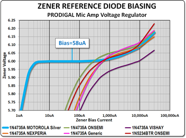
Razor-Flat Blue Line of the Vintage
Motorola Diode
|
|
5. Assembly
All Audio Boards |
Front Panel Contol Boards |
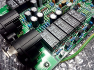
Installation of the Prodigal circuit boards is fairly straightforward,
but they still want to be handled like new-born puppies. There
are three control boards for the front panel, six in/outs for
the rear, and the power supply makes an even ten. Once they're
all fitted, six IDC ribbon cables similar to those used in
computers provide the complete network of inter-board power and
signal busses. Prior to insertion, connection pins are cleaned,
and connectors are sprayed with electro-lube.
Much has been done to suppress or eliminate
electromagnetic interference within the unit. Each board has a
guard-ring etched around its perimeter to shunt radiated energy
away from audio and back to ground. Along the ribbon cables, no
two signals travel side by side; instead, they are always
separated by a grounded strand that guards against one
signal-pair injecting crosstalk into another. There are actually
more strands used as guards than for any other purpose.
Furthermore, power and signal are never allowed on the same
ribbon.
As hinted above, audio travels along the buss in
balanced pairs, which is an unusually fussy arrangement for
board-to-board signals. This is so any received radiation not
whisked away by the guard-strands can be cancelled by a balanced
receiver at the end of each line.
All the careful design work which focussed on the
extraction of unwanted signals has paid off in silence, with
input noise way down at -118dBu, and remarkably, mains hum
levels (unmeasurably) even lower than that.
|
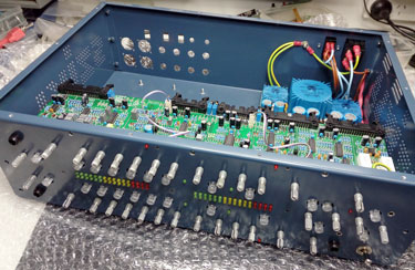
Front Boards In |
Rear Panel In-Out Boards |
|
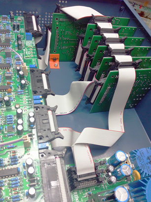
All Buss Lines In |
|
All Boards In |
|
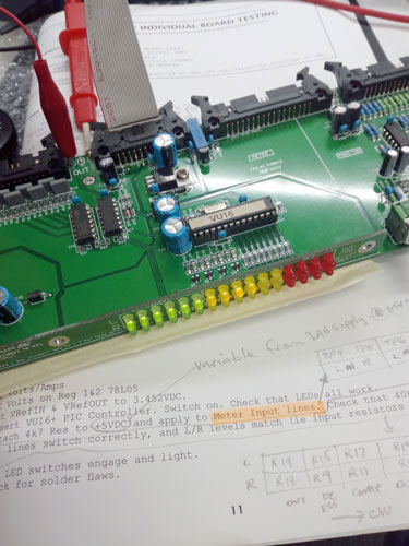
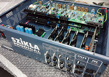
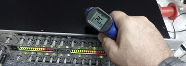
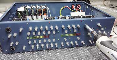
6. Testing and
Aligning
All Systems |
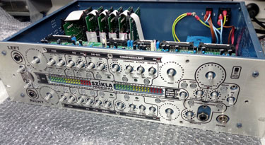
Temporary Dummy Front Fascia |
Nobody wants to get testy during testing, so a dummy
front fascia is attached to
ease the headache of wondering which knob is which. Afterwards,
the dummy will be replaced by a pristine real one. Knobs and
other scratchable externals also stay under wraps until the last possible moment.
First up, the power buss is broken out into its
seven separate rails, which are checked against expectation
under various load conditions, and any Prodigal inconsistencies
are corrected.
When we are satisfied that the heart is beating
correctly and the blood is pumping where it should, we move on
to inspect the athletic and artistic properties of the
Prodigal's audio circuits. There are tests for each side of the
channel strip, more tests for the monitor section, and it takes
about four and a half hours to run through the full checklist.
Every input and output is examined, and a number of internal
settings are tweaked for critical performance and optimum
channel match.
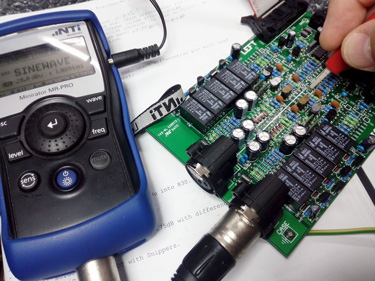
The main audio signal injected is a pure
sine-wave, which facilitates reliable analyses of amplitude,
bandwidth, headroom, equalisation and distortion. Besides inputs
and outputs, readings are also taken at the L-R mix buss, and
other internal nodes. Sexy and highly accurate test equipment is
employed, to measure levels, baffle our friends and relatives,
and make us look very clever. (Trivia sidenote: even though the
idea has been workshopped by every technician in the last fifty
years, not a single one of these machines dispenses coffee.)
Eventually the form below is transcribed into a
forest of ticks and scribbles, all the audio paths are tuned to
perfection, and we are ready for final assembly.
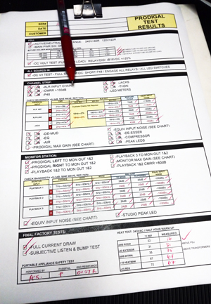 |
Measuring Current Draw Along All The
Supply Rails At The Same Time |
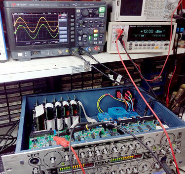
Sinewave Analysis Using Raunchy Electro-Porn Gadgets |
|
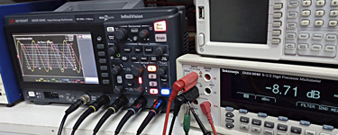
Graphing Bandwidth |
|
7. Final assembly |
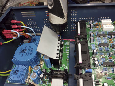
Adding The Cooling Fin |
First among the last things, we add an additional cooling fin to the power
supply, to draw away as much heat as possible and direct it towards the rear vents.
Then we put the lid on, and try to make the Prodigal hotter than you
are ever likely to experience it! The unit is warmed up for thirty minutes
with all LED switches on, audio clipped beyond saturation, and
the headphone amp turned up loud but playing into a
short-circuit
failure condition. We take its temperature at specific
external and internal nodes, and are yet to witness a complaint. As we said earlier, we didn't want
a fan, because fans make noise, and the Prodigal is dead
silent.
Following that torsion ordeal, the unit receives
the final
standard appliance safety test, to double-check for insulation and earth
continuity compliance.
Hooray! Now we get to fit all the good-looking
bits, and enjoy the finished product.
Off comes the dummy fascia, and on go the
potentiometer nuts. They've been kept aside till now so that
any board requiring inspection can be easily removed. A shiny
new fascia and two gold rack ears are unwrapped and fastened with hex-head
machine screws. Now the unit is finally looking like a Prodigal.
Knobs and switch-caps all get the cotton-glove
treatment... and suddenly we are done!
But wait, there's more. Before sending our baby
out into the world, there's still an important box to tick: a live
listening test with microphones, playback, headphones and nearfield monitors. This is
our favourite test, partly
because a love of listening to (loud) audio is why we started doing this for a
living in the first place, and partly because after all that
painstaking work it feels like we're just kicking back and sipping a
coffee that took us a week to get to. mmmm. Stairway to arabica!
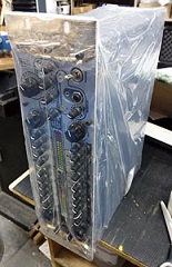
When the neighbours start banging on our windows,
the Prodigal gets a quick polish, goes into a plastic bag and foam protectors, and
is put snugly to sleep in a double-corrugated
cardboard carton for shipping off around the world.
We are extremely proud of our Prodigal Channel
Strip, which
while still in its relative infancy has been used to create some
outstanding recordings, and is waiting to help you with yours.
I hope you have enjoyed this blog, and I thank you
for reading it. If you would like to try a Prodigal, or have any
comments or questions we would love to hear from you.
- Andy Szikla
 |
Heat Check Under Crazy Load Conditions |
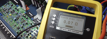
Appliance Safety Test |
Going Nuts |
|
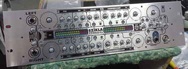
Shiny
New Fascia... |
And Rack Ears |
|
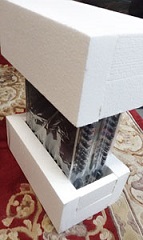
Bagged And Foamed, Ready For Boxing |

Knobs And Other Fittings |
back
to top
|